This chapter presents a broad overview of computer networking and the Internet.
What Is the Internet
A Nuts-and-Bolts Description
The Internet is a computer network that interconnects hundreds of millions of com-puting devices throughout the world.
End systems are connected together by a network of communication links and packet switches.
communication links, which are made up of different types of physical media, including coaxial cable, copper wire, optical fiber, and radio spectrum.
Packet switches come in many shapes and flavors, but the two most prominent types in today’s Internet are routers and link-layer switches.
The sequence of communication links and packet switches traversed by a packet from the sending end system to the receiving end system is known as a route or path through the network.
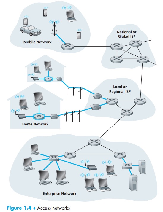
End systems access the Internet through Internet Service Providers (ISPs).
Each ISP is in itself a network of packet switches and communication links. ISPs provide a variety of types of network access to the end systems.ISPs also provide Internet access to content providers, connecting Web sites directly to the Internet.
Internet stan-dards are developed by the Internet Engineering Task Force (IETF)[IETF 2012]. The IETF standards documents are called requests for comments (RFCs).
A Service Description
But we can also describe the Internet from an entirely different angle—namely, as an infrastructure that provides services to applications.
These applications include electronic mail, Web surfing, social networks, instant messaging, Voice-over-IP(VoIP), video streaming, distributed games, peer-to-peer (P2P) file shar-ing, television over the Internet, remote login, and much, much more.
End systems attached to the Internet provide an Application Programming Interface (API).
What Is a Protocol
A protocol defines the format and the order of messages exchanged between two or more communicating entities, as well as the actions taken on the trans-mission and/or receipt of a message or other event.
End systems, packet switches, and other pieces of the Internet run protocols that control the sending and receiving of information within the Internet.
Transmission Control Protocol (TCP) and the Internet Protocol (IP).
The Network Edge
Access Networks
host = end system. Hosts are sometimes further divided into two categories: clients and servers.
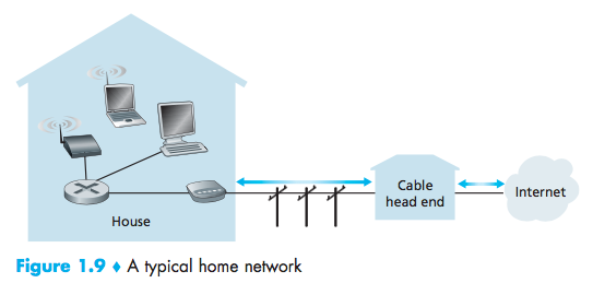
Home Access: DSL, Cable, FTTH, Dial-Up, and Satellite
Today, the two most prevalent types of broadband residential access are digital subscriber line (DSL) and cable.
DSL
Each customer’s DSL modem uses the existing telephone line to exchange data with a digital subscriber line access multiplexer (DSLAM) located in the telco’s local central office (CO).
The residential telephone line carries both data and traditional telephone sig-nals simultaneously, which are encoded at different frequencies:
- A high-speed downstream channel, in the 50 kHz to 1 MHz band
- A medium-speed upstream channel, in the 4 kHz to 50 kHz band
- An ordinary two-way telephone channel, in the 0 to 4 kHz band

Cable
cable Internet access makes use of the cable television company’s existing cabletelevision infrastructure.
hybrid fiber coax (HFC)
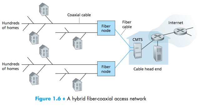
cable modem termination system (CMTS)
The DOCSIS 2.0 standard defines downstream rates up to 42.8 Mbps and upstream rates of up to 30.7 Mbps.
One important characteristic of cable Internet access is that it is a shared broadcast medium. In particular, every packet sent by the head end travels down- stream on every link to every home and every packet sent by a home travels on the upstream channel to the head end.
FTTH
fiber to the home (FTTH)
provide an optical fiber path from the CO directly to the home.
Two competing optical-distribution network architectures that perform this splitting: active optical networks (AONs) and passive optical net- works (PONs).
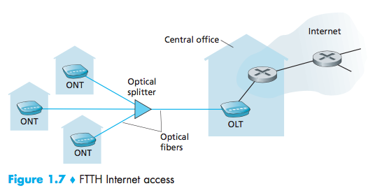
optical network terminator (ONT)
optical line terminator (OLT)
Dial-Up
Dial-up access over traditional phone lines is based on the same model as DSL—a home modem connects over a phone line to a modem in the ISP. Compared with DSL and other broadband access networks, dial-up access is excru- ciatingly slow at 56 kbps.
Satellite
A satellite link can be used to connect a residence to the Inter- net at speeds of more than 1 Mbps.
Enterprise Access: Ethernet and WiFi
Ethernet
local area network (LAN)
Ethernet users use twisted-pair copper wire to connect to an Ethernet switch.
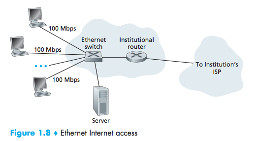
users typically have 100 Mbps access to the Ethernet switch, whereas servers may have 1 Gbps or even 10 Gbps access.
WiFi
Wireless LAN access, provides a shared transmission rate of up to 54 Mbps.
Wide-Area Wireless Access: 3G and LTE
3G and LTE
third-generation (3G) wireless
a fourth-generation (4G) of wide-area wireless networks
LTE(Long-Term Evolution)
Physical Media
Physical media fall into two categories: guided(solid) media and unguided(atmosphere) media.
Twisted-Pair Copper Wire
The least expensive and most commonly used guided transmission medium is twisted-pair copper wire.
Unshielded twisted pair (UTP)
Coaxial Cable
Coaxial cable consists of two copper conductors, but the two con- ductors are concentric rather than parallel.
Fiber Optics
A thin, flexible medium that conducts pulses of light, with each pulse representing a bit.
The Optical Carrier (OC) standard link speeds range from 51.8 Mbps to 39.8 Gbps; these specifications are often referred to as OC- n, where the link speed equals n × 51.8 Mbps. Standards in use today include OC-1, OC-3, OC-12, OC-24, OC-48, OC-96, OC-192, OC-768.
Terrestrial Radio Channels
Radio channels carry signals in the electromagnetic spectrum.
The wireless LAN technologies described use local-area radio channels; the cellular access technologies use wide-area radio channels.
Satellite Radio Channels
Geostationary satellites and low-earth orbiting (LEO) satellites.
Geostationary satellites permanently remain above the same spot on Earth.LEO satellites are placed much closer to Earth and do not remain permanently above one spot on Earth.
The Network Core
Packet Switching
The source breaks long messages into smaller chunks of data known as packets.
Store-and-forward transmission
Store-and-forward transmission means that the packet switch must receive the entire packet before it can begin to transmit the first bit of the packet onto the outbound link.
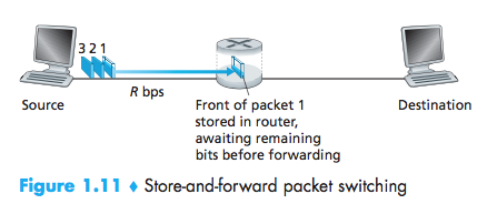
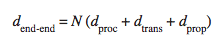
End-to-end delay:Sending one packet from source to desti- nation over a path consisting of N links each of rate R
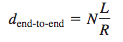
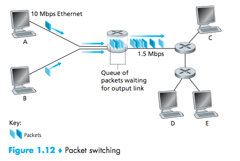
Queuing Delays and Packet Loss
For each attached link, the packet switch has an output buffer (also called an output queue)
queuing delays
packet loss will occur—either the arriving packet or one of the already-queued packets will be dropped.
Forwarding Tables and Routing Protocols
Each router has a forwarding table that maps destination addresses (or portions of the destination addresses) to that router’s outbound links.
Routing protocols that are used to automatically set the forwarding tables.
A routing protocol may, for example, determine the shortest path from each router to each destination and use the shortest path results to configure the forwarding tables in the routers.
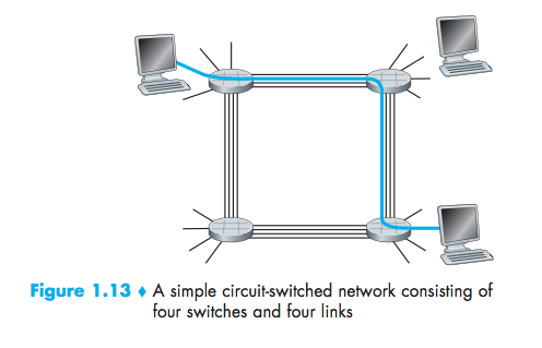
Circuit Switching
In circuit-switched networks, the resources needed along a path (buffers, link transmission rate) to provide for communication between the end systems are reserved for the duration of the communication session between the end systems.
The sender can transfer the data to the receiver at the guaranteed constant rate.
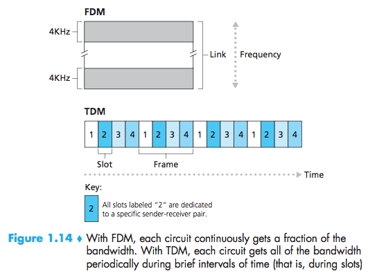
Multiplexing in Circuit-Switched Networks
frequency-division multiplexing(FDM) or time-division multiplexing (TDM)
With FDM, the frequency spec-trum of a link is divided up among the connections established across the link.
For a TDM link, time is divided into frames of fixed duration, and each frameis divided into a fixed number of time slots.
Packet Switching Versus Circuit Switching
Circuit switching pre-allocates use of the transmission link regard-less of demand, with allocated but unneeded link time going unused. Packet switching on the other hand allocates link use on demand. Link transmission capac-ity will be shared on a packet-by-packet basis only among those users who have packets that need to be transmitted over the link.
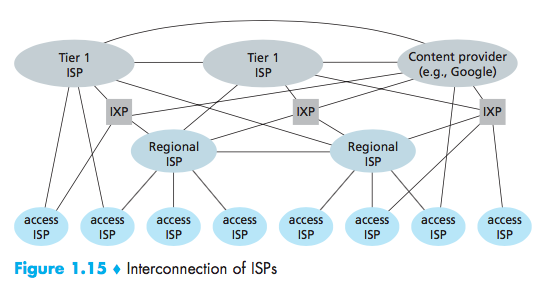
A Network of Networks
points of presence (PoPs), multi-homing, peering, and Internet exchange points(IXPs)
A PoP is simply a group of one or more routers (at the same location) in the provider’s network where customer ISPs can connect into the provider ISP.
Any ISP(except for tier-1 ISPs) may choose to multi-home, that is, to connect to two or more provider ISPs.
A pair of nearby ISPs at the same level of the hierarchy can peer, that is, they can directly connect their networks together.
Internet Exchange Point (IXP)(typically in a stand-alone building with its own switches), which is a meeting point where multiple ISPs can peer together.
Delay, Loss, and Throughput in Packet-Switched Networks
The physical laws of real- ity introduce delay and loss as well as constrain throughput.
Overview of Delay in Packet-Switched Networks
Total nodal delay:nodal processing delay, queuing delay, transmis-sion delay, and propagation delay
Processing Delay
The time required to examine the packet’s header and determine where to direct the packet is part of the processing delay.
microseconds
Queuing Delay
At the queue, the packet experiences a queuing delay as it waits to be transmitted onto the link.
microseconds to milliseconds
Transmission Delay
The transmission delay is L(bits)/R(bits/sec). This is the amount of time required to push (that is, transmit) all of the packet’s bits into the link.
microseconds to milliseconds
Propagation Delay
The time required to propagate from the beginning of the link to router B is the propagation delay.
Queuing Delay and Packet Loss
traffic intensity:The ratio La/R (L bits, a is in units of packets/sec, R is the transmission rate)
Nth packet transmitted has a queuing delay of(n-1)L/R seconds.
The traffic intensity is close to zero, then packet arrivals are few and far between, the average queuing delay will be close to zero.When the traffic intensity is close to 1, there will be intervals of time when the arrival rate exceeds the transmission capacity.
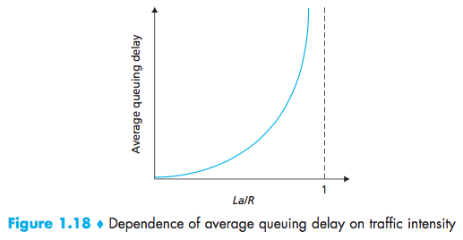
With no place to store such a packet, a router will drop that packet; that is, the packet will be lost.
End-to-End Delay
N links, suppose for the moment that the network is uncon- gested (so that queuing delays are negligible):
Traceroute
The source will send N special packets into the network, When the nth router receives the nth packet marked n, the router does not forward the packet toward its destination, but instead sends a message back to the source. The source reconstruct the route taken by packets flowing from source to destination, and the source can determine the round-trip delays:
Traceroute actually repeats the experiment just described three times, so the source actually sends 3 • N packets to the destination.
1 | ID | Title | Round-trip Delays |
Traceroute places an asterisk just after the router number and reports fewer than three round-trip times for that router.(Further, but return faster)
End System, Application, and Other Delays
Additional significant delays:purposefully delay & media packetization delay.
Purposefully delay:an end system wanting to transmit a packet into a shared medium.
Media packetization delay:In VoIP, the sending side must first fill a packet with encoded digitized speech before passing the packet to the Internet.
Throughput in Computer Networks
The instantaneous throughput at any instant of time is the rate(in bits/sec) at which Host B is receiving the file.
If the file consists of F bits and the transfer takes T seconds for Host B to receive all F bits, then the average throughput of the file transfer is F/T bits/sec.
bottleneck link:min{R1, R2,…, RN}
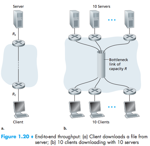
the throughput can simply be approximated as the minimum transmission rate along the path between source and destination.
Protocol Layers and Their Service Models
Protocol Layering

Application Layer
The application layer is where network applications and their application-layer proto-cols reside.
HTTP SMTP FTP DNS
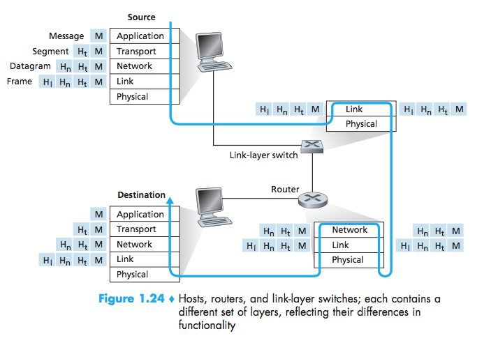
Message:a application-layer packet
An application-layer protocol is distributed over multiple end systems.
Transport Layer
The Internet’s transport layer transports application-layer messages between application endpoints.
TCP UDP
Segment:a transport-layer packet
Network Layer
The Internet’s network layer is responsible for moving network-layer packets known as datagrams from one host to another.
IP Routing
Datagram:a Network-layer packet
Link Layer
The link layer, which delivers the datagram to the next node along the route.
Ethernet, WiFi, and the cable access network’s DOCSIS protocol
Frame:a Link-layer packet
Physical Layer
The job of the physical layer is to move the individ-ual bits within the frame from one node to the next.
The protocols in this layer are again link dependent and further depend on the actual transmission medium of the link (for example, twisted-pair copper wire, single-mode fiber optics).
Bit:A bit is moved across the link in a different way.
Presentation Layer
The role of the presentation layer is to provide services that allow communicating applications to interpret the meaning of data exchanged.
data compression, data encryption, data description
Session Layer
The session layer provides for delimiting and synchronization of data exchange, includ-ing the means to build a checkpointing and recovery scheme.
delimiting and synchronization of data exchange
Encapsulation
Each layer, a packet has two types of fields: header fields and a payload field.
Networks Under Attack
The bad guys can put malware into your host via the Internet
Botnet:which the bad guys control and leverage for spam e-mail distribution or distributed denial-of-service attacks (soon to be discussed) against targeted hosts.
Self-replicating
Malware can spread in the form of a virus or a worm. Viruses are malware that require some form of user interaction to infect the user’s device.Worms are malware that can enter a device without any explicit user interaction.
The bad guys can attack servers and network infrastructure
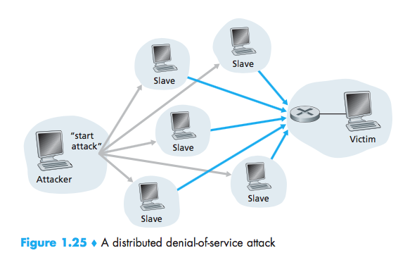
denial-of-service (DoS) attacks:renders a network, host, or other piece of infrastructure unusable by legitimate users.
Most Internet DoS attacks fall into one of three categories:
- Vulnerability attack:This involves sending a few well-crafted messages to a vulnerable application or operating system running on a targeted host.
- Bandwidth flooding:The attacker sends a deluge of packets to the targeted hos
- Connection flooding:The attacker establishes a large number of half-open or fully open TCP connections.
distributed DoS (DDoS)
The bad guys can sniff packets
Packet sniffer:A passive receiver that records a copy of every packet that flies by.
The bad guys can masquerade as someone you trust
IP spoofing:The ability to inject packets into the Internet with a false source address.
To solve this problem, we will need end-point authentication.