This chapter we study the critical role of providing com- munication services directly to the application processes running on different hosts.
Residing between the application and network layers, the transport layer is a central piece of the layered network architecture.
Introduction and Transport-Layer Services
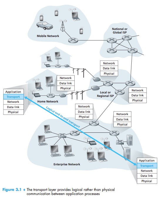
A transport-layer protocol provides for logical communication between appli-cation processes running on different hosts. By logical communication, we mean that from an application’s perspective, it is as if the hosts running the processes were directly connected; in reality, the hosts may be on opposite sides of the planet, connected via numerous routers and a wide range of link types.
The transport layer breaking the application messages into smaller chunks and adding a transport-layer header to each chunk to create the transport-layer segment.
Relationship Between Transport and Network Layers
Whereas a transport-layer protocol provides logical communication between processes running on different hosts, a network-layer protocol provides logical communication between hosts.
Overview of the Transport Layer in the Internet
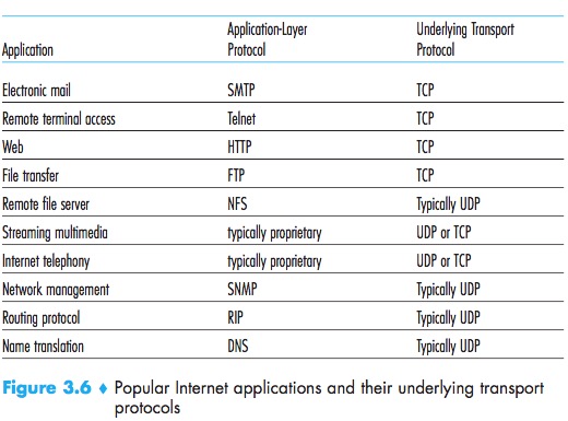
Two distinct transport-layer protocols available to the application layer. One of these protocols is UDP (User Datagram Protocol), which provides an unreliable, connectionless service to the invoking application. The second of these protocols is TCP (Transmission Con- trol Protocol), which provides a reliable, connection-oriented service to the invoking application.
The IP service model is a best-effort delivery service. It makes no guarantees. IP is said to be an unreliable service.
Extending host-to-host delivery to process-to-process delivery is called transport-layer multiplexing and demultiplexing. UDP and TCP also provide integrity checking by including error-detection fields in their segments’headers.
These two minimal transport-layer services process-to-process data delivery and error checking are the only two services that UDP provides.
UDP:process-to-process data delivery, error checking
TCP:process-to-process data delivery, error checking, reliable data transfer, congestion control
Multiplexing and Demultiplexing
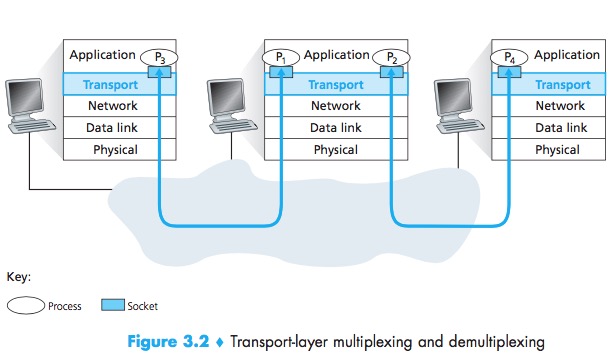
Transport-layer Multiplexing and Demultiplexing:extending the host-to-host delivery service provided by the network layer to a process-to-process delivery service for applications running on the hosts.
The transport layer in the receiving host does not actually deliver data directly to a process, but instead to an intermediary socket.
Demultiplexing:This job of delivering the data in a transport-layer segment to the correct socket.
Multiplexing:The job of gathering data chunks at the source host from different sockets, encapsulating each data chunk with header information (that will later be used in demultiplexing) to create segments, and passing the segments to the network layer.
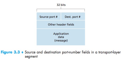
Source port number field & Destination port number field:Each port number is a 16-bit number, ranging from 0 to 65535. The port numbers ranging from 0 to 1023 are called well-known port numbers and are restricted, which means that they are reserved for use by well-known application protocols.
Connectionless Multiplexing and Demultiplexing
UDP:same destination IP address & destination port number -> the same destination socket.
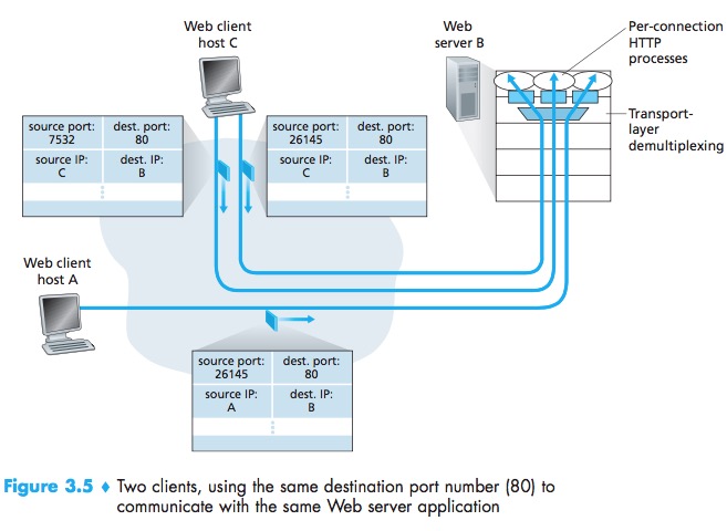
Connection-Oriented Multiplexing and Demultiplexing
A TCP socket is identified by a four-tuple: (source IP address, source port number, destination IP address, destination port number).
TCP:same destination IP address & destination port number -> different destination socket.
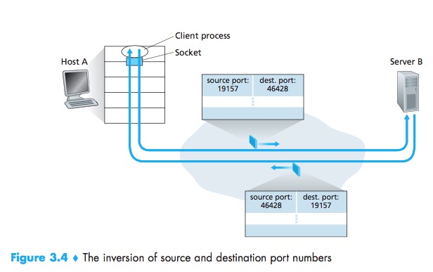
The server host may support many simultaneous TCPconnection sockets, with each socket attached to a process, and with each socket identified by its own four-tuple. When a TCP segment arrives at the host, all four fields (source IPaddress,source port, destination IPaddress, destination port) are used to direct (demultiplex)the segment to the appropriate socket.
Web Servers and TCP
Today’s high-performing Web servers often use only one process, and create a new thread with a new connection socket for each new client connection.
Connectionless Transport: UDP
UDP:does just about as little as a transport protocol can do. Aside from the multiplexing/demultiplexing function and some light error checking, it adds nothing to IP.UDP is said to be connectionless.
DNS:an example of an application-layer protocol that typically uses UDP.If it doesn’t receive a reply, either it tries sending the query to another name server, or it informs the invoking application that it can’t get a reply.
Many applications are better suited for UDP for the following reasons:
- Finer application-level control over what data is sent, and when:real-time applications;
- No connection establishment:DNS would be much slower if it ran over TCP;
- No connection state;
- Small packet header overhead.
When packet loss rates are low, and with some organizations blocking UDP traffic for security reasons , TCP becomes an increasingly attractive protocol for streaming media transport.
The lack of congestion control in UDP can result in high loss rates between a UDP sender and receiver, and the crowding out of TCP sessions—a potentially serious problem.
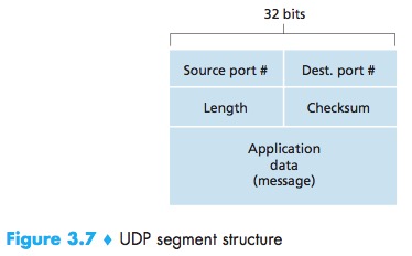
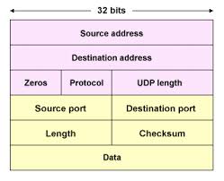
UDP Segment Structure
The UDP header has only four fields, each consisting of two bytes:
- Source port;
- Dest port;
- The length field:specifies the number of bytes in the UDP segment (header plus data);
- The checksum field:used by the receiving host to check whether errors have been introduced into the segment.
UDP Checksum
Checksum:used to determine whether bits within the UDP segment have been altered (for example, bynoise in the links or while stored in a router) as it moved from source to destination.
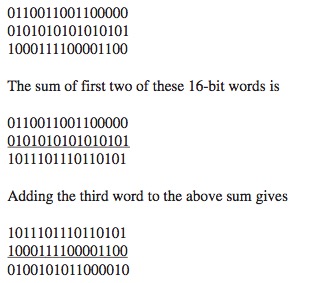
The checksum calculation:add all the datas(Pseudo UDP header, UDP header, data) bits by 16-bit, and filp the result(0->1, 1->0).
The Pseudo UDP header also consists of 5 fields:
- source address: 32 bits/4 bytes, taken from IP header
- destination address: 32 bits/4 bytes, taken from IP header
- reserved: 8 bits/1 byte, set to all 0s.
- protocol: 8 bits/1 byte, taken from IP header
- length: Because UDP header has a length field that indicates the length of the entire datagram, including UDP header and data, the value from UDP header is used. Note that this is different from TCP pseudo header, which is computed on the fly. But they both indicates the header+payload length.
why UDP provides a checksum in the first place(end-end principle), as many link- layer protocols (including the popular Ethernet protocol) also provide error checking:
- no guarantee that all the links between source and destinationprovide error checking;
- it’s possible that bit errors could be introduced when a segment is stored in a router’s memory.
But UDP does not do anything to recover from an error.
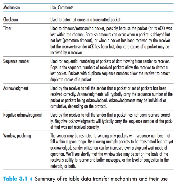
Principles of Reliable Data Transfer
A Reliable Data Transfer Protocol:With a reliable channel, no transferred data bits are corrupted (flipped from 0 to 1, or vice versa) or lost, and all are delivered in the order in which they were sent.
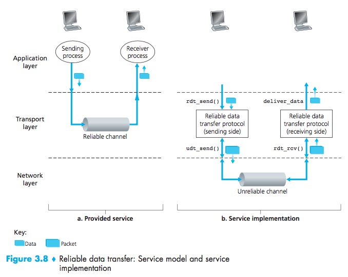
Building a Reliable Data Transfer Protocol
Reliable Data Transfer over a Perfectly Reliable Channel: rdt1.0
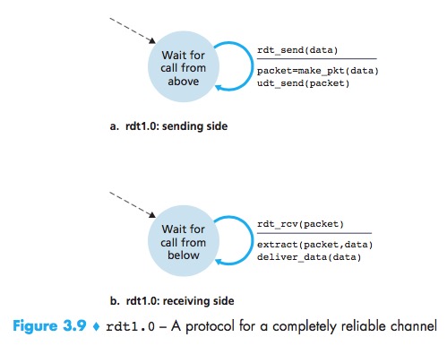
^:means no action
with a perfectly reliablechannel there is no need for the receiver side to provide any feedback to the sendersince nothing can go wrong. No need forthe receiver to ask the sender to slow down.
Reliable Data Transfer over a Channel with Bit Errors: rdt2.0
ACK:positive acknowledgments(“OK”)
NDK:negative acknowledgments (“Please repeat that.”)
In a computer network setting, reliable data transfer protocols based on such retransmission are known as ARQ (Automatic Repeat reQuest) protocols.
Three additional protocol capabilities to handle the presence of bit errors:
- Error detection:A mechanism is needed to allow the receiver to detect when bit errors have occurred. These techniques require that extra bits be sent from the sender to the receiver; these bits will be gathered into the packet checksum field of the rdt2.0 data packet;
- Receiver feedback:The ACK and NAK acknowledgment replies in the message-dictation scenario are examples of such feedback. Our rdt2.0 protocol will similarly send ACK and NAK packets back from the receiver to the sender;
- Retransmission:A packet that is received in error at the receiver will be retransmitted by the sender.
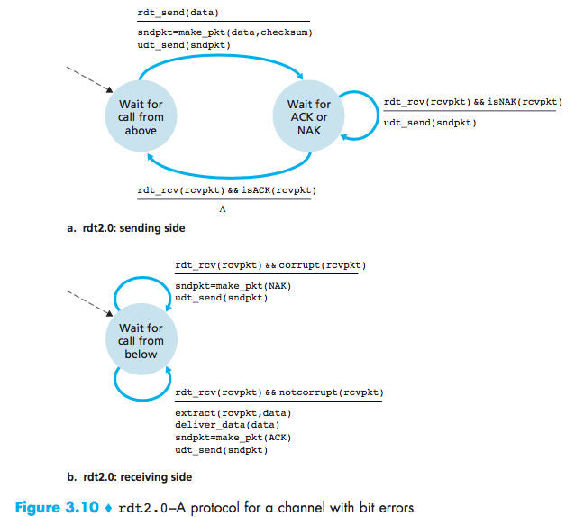
stop-and-wait protocols
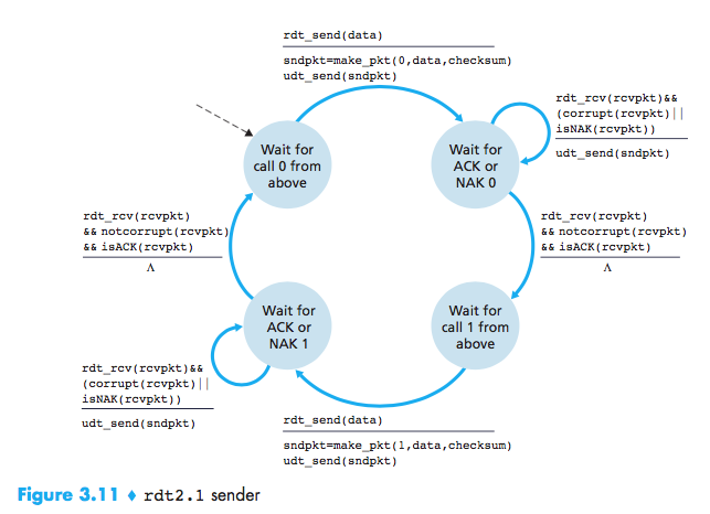
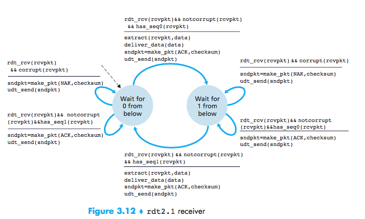
Reliable Data Transfer over a Channel with Bit Errors: rdt2.1
But the ACK or NAK packet could be corrupted and how the protocol should recover from errors in ACK or NAK packets?
A simple solution is to add a new field and putting a sequence number into this field. The receiver then need only check this sequence number to determine whether or not the received packet is a retransmission. For this simple case of a stop-and-wait protocol, a 1-bit sequence number will suffice, since it will allow the receiver to know whether the sender is resending the previously transmitted packet or a new packet.
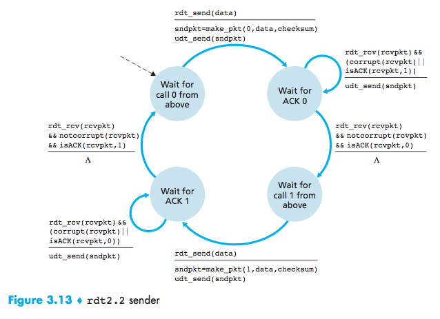
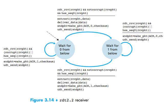
NAK-free Reliable Data Transfer over a Channel with Bit Errors: rdt2.2
We can send an ACK for the last correctly received packet. A sender that receives two ACKs for the same packet (that is, receives duplicate ACKs) knows that the receiver did not correctly receive the packet following the packet that is being ACKed twice.
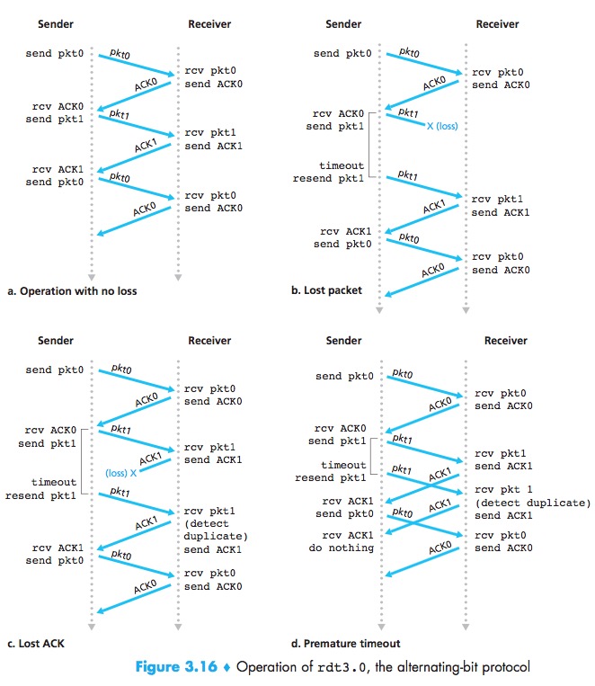
Reliable Data Transfer over a Lossy Channel with Bit Errors: rdt3.0
Timeout to retransmit:Implementing a time-based retransmission mechanism requires a countdown timer that can interrupt the sender after a given amount of time has expired.
Because packet sequence numbers alternate between 0 and 1, protocol rdt3.0 is sometimes known as the alternating bit protocol.
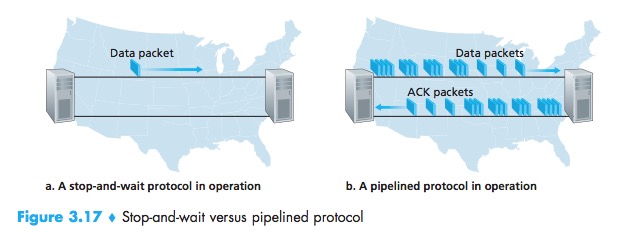
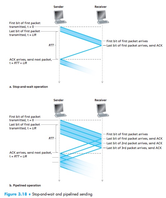
At the heart of rdt3.0’s performance problem is the fact that it is a stop-and-wait protocol.
Pipelined Reliable Data Transfer Protocols
Pipelining has the following consequences for reliable data transfer protocols:
- The range of sequence numbers must be increased, since each in transit packet must have a unique sequence number;
- The sender and receiver sides of the protocols may have to buffer more than one packet.
- The range of sequence numbers needed and the buffering requirements will depend on the manner in which a data transfer protocol responds to lost, corrupted, and overly delayed packets.
Two basic approaches toward pipelined error recovery can be identified: Go-Back-N and selective repeat.
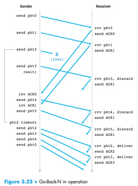
Go-Back-N(GBN)
GBN:the sender is allowed to transmit multiple packets without waiting for an ACK, but is constrained to have no more than some maximum allowable number, N, of unacknowledged packets in the pipeline.
Sliding-Window Protocol:
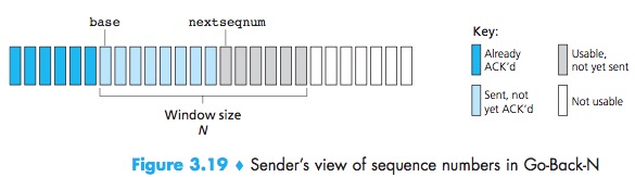
If k is the number of bits in the packet sequence number field, the range of sequence numbers is thus [0, $2^k$ – 1]. With a finite range of sequence numbers, all arithmetic involving sequence numbers must then be done using modulo $2^k$ arithmetic.
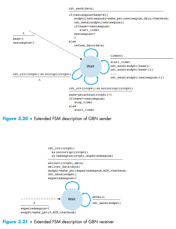
The GBN sender must respond to three types of events:
- Invocation from above:When rdt_send() is called, the sender first checks to see if the window is not full, a packet is created and sent, and variables are appropriately updated;
- Receipt of an ACK:An ACK for a packet with sequence number n will be taken to be a cumulative ACK, indicating that all packets with a sequence number up to and including n have been correctly received at the receiver;
- A timeout event:The sender resends all packets that have been previously sent but that have not yet been acknowledged.If an ACK is received but there are still additional transmitted but not yet acknowledged packets, the timer is restarted. If there are no outstanding, unacknowledged packets, the timer is stopped.
In bad cases, the receiver discards the packet and resends an ACK for the most recently received in order packet.The advantage of this approach is the simplicity of receiver buffering—the receiver need not buffer any out-of-order packets.
Selective Repeat(SR)
SR:avoid unnecessary retransmissions by having the sender retransmit only those packets that it suspects were received in error at the receiver.
The SR receiver will ACK a correctly received packet whether or not it is in order. Out-of-order packets are buffered until any missing packets are received.
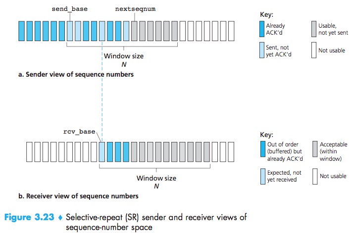
The sender make each packet have its own logical timer.the receiver reACK already received packets with certain sequence numbers below the current window base.If there is no ACK for packet send_base propagating from the receiver to the sender, the sender will eventually retransmit packet send_base.
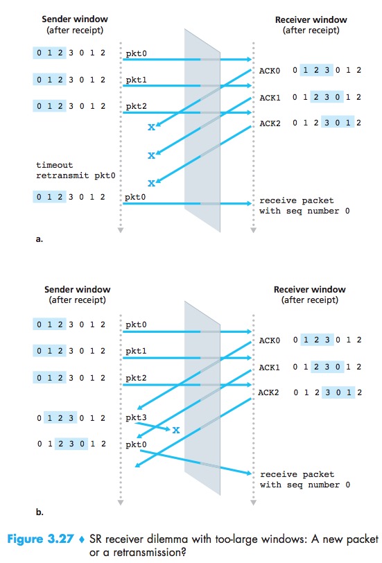
Because sequence numbers may be reused, some care must be taken to guard against such duplicate packets.This is done by assuming that a packet cannot “live” in the network for longer than some fixed maximum amount of time. A maximum packet lifetime of approximately three minutes is assumed in the TCP extensions for high-speed networks.
Summary
Connection-Oriented Transport: TCP
The TCP Connection
connection-oriented, full-duplex service(double-sided
), point-to-point
MTU(maximum transmission unit):the length of the largest link-layer frame that can be sent by the local sending host.
MSS(maximum segment size):the maximum amount of application-layer data in the segment, not the maximum size of the TCP segment including headers.
The MSS is typically set by first determining MTU, and then setting the MSS to ensure that a TCP segment plus the TCP/IP header length (typically 40 bytes) will fit into a single link-layer frame. Both Ethernet and PPP link-layer protocols have an MSS of 1,500 bytes.
TCP Segment Structure
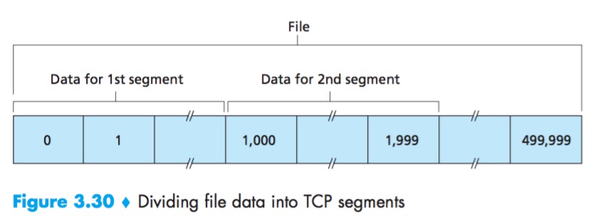
When TCP sends a large file, it typically breaks the file into chunks of size MSS.
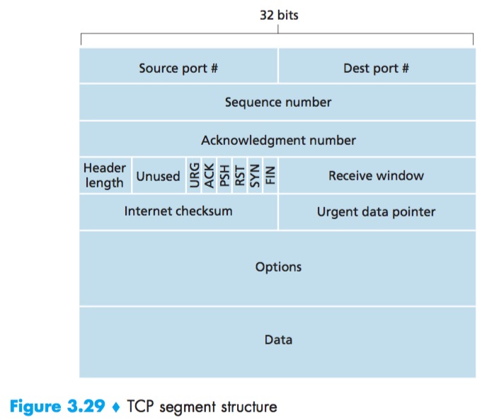
A TCP segment header also contains the following fields:
- The 16-bit receive window field is used for flow control;
- The 4-bit header length field specifies the length of the TCP header in 32-bit words. The TCP header can be of variable length due to the TCP options field.
(Typically, the options field is empty, so that the length of the typical TCP header is 20 bytes.) - The optional and variable-length options field is used when a sender and receiver negotiate the MSS or as a window scaling factor for use in high-speed networks;
- The flag field contains 6 bits. The RST, SYN, and FIN bits are used for connection setup and teardown; Setting the RST bit indicates that this host doesn’t have a socket, tell the client don’t resend the segement,Setting the PSH bit indicates that the receiver should pass the data to the upper layer immediately; Finally, the URG bit is used to indicate that there is data in this segment that the sending-side upper-layer entity has marked as “urgent.”
- The location of the last byte of this urgent data is indicated by the 16-bit urgent data pointer field. TCP must inform the receiving-side upper-layer entity when urgent data exists and pass it a pointer to the end of the urgent data. (In practice, the PSH, URG, and the urgent data pointer are not used.)
Sequence Numbers and Acknowledgment Numbers
Sequence Number:the byte-stream number of the first byte in the segment.
The TCP will implicitly number each byte in the data stream.
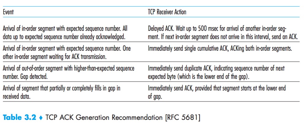
Acknowledgment Number:the sequence number of the next byte Host A is expecting from Host B.
Because TCP only acknowledges bytes up to the first missing byte in the stream, TCP is said to provide cumulative acknowledgments.
In truth, both sides of a TCP connection randomly choose an initial sequence number. This is done to minimize the possibility that a segment that is still present in the network from an earlier, already-terminated connection between two hosts is mistaken for a valid segment in a later connection between these same two hosts.
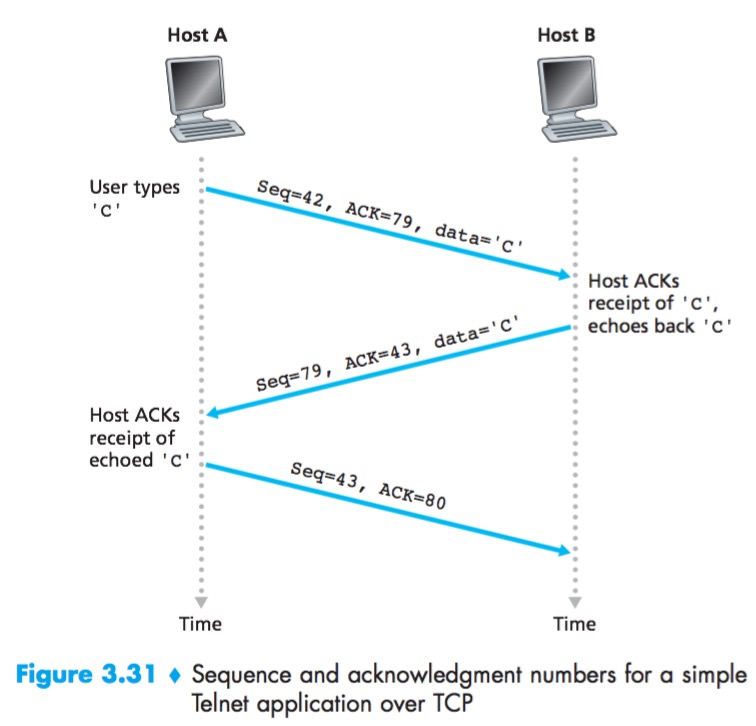
Telnet
Telnet: a popular application-layer protocol used for remote login.
Each character typed by the user (at the client) will be sent to the remote host; the remote host will send back a copy of each character, which will be displayed on the Telnet user’s screen. This “echo back” is used to ensure that characters seen by the Telnet user have already been received and processed at the remote site. Each character thus traverses the network twice between the time the user hits the key and the time the character is displayed on the user’s monitor.
The acknowledgment for client-to-server data is carried in a segment carrying server-to-client data; this acknowledgment is said to be piggybacked on the server-to-client data segment.
Round-Trip Time Estimation and Timeout
Estimating the Round-Trip Time
SampleRTT:the amount of time between when the segment is sent and when an acknowledgment for the segment is received.
TCP maintains an average, called EstimatedRTT:
$$EstimatedRTT = (1 - α) EstimatedRTT + α SampleRTT$$
Such an average is called an exponential weighted moving average (EWMA).
DevRTT, as an estimate of how much SampleRTT typically deviates from EstimatedRTT:
$$DevRTT = (1 - β) DevRTT + β | SampleRTT - EstimatedRTT |$$
Setting and Managing the Retransmission Timeout Interval
Retransmission timeout interval:
$$TimeoutInterval = EstimatedRTT + 4 * DevRTT$$
An initial TimeoutInterval value of 1 second is recommended. Also, when a timeout occurs, the value of TimeoutInterval is doubled to avoid a premature timeout occurring for a subsequent segment that will soon be acknowledged. However, as soon as a segment is received and EstimatedRTT is updated, the TimeoutInterval is again computed using the formula above.
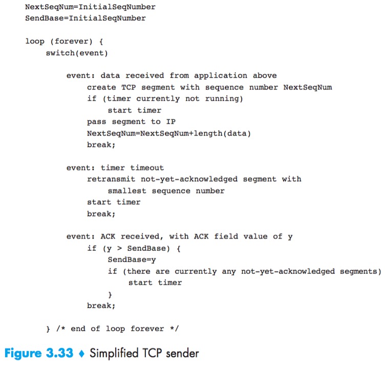
Reliable Data Transfer
The recommended TCP timer management procedures use only a single retransmission timer, even if there are multiple transmitted but not yet acknowledged segments.
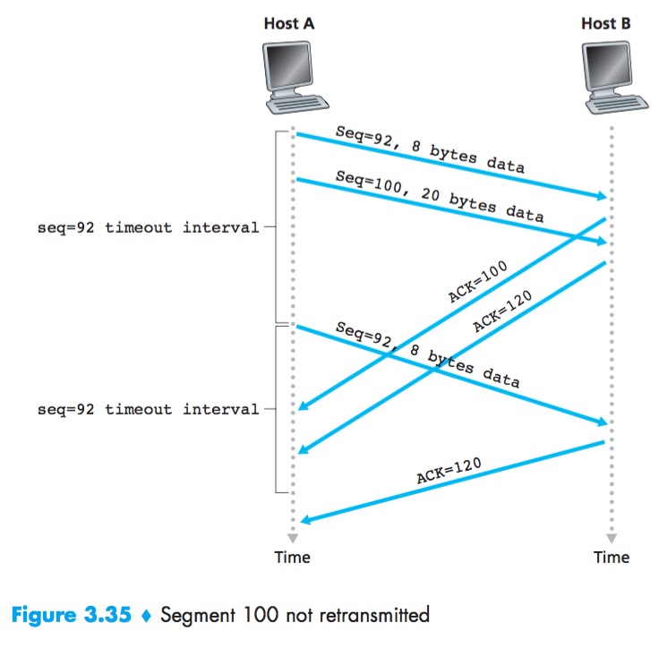
The TCP state variable SendBase is the sequence number of the oldest unacknowledged byte.
Doubling the Timeout Interval
Each time TCP retransmits, it sets the next timeout interval to twice the previous value, rather than deriving it from the last EstimatedRTT and DevRTT.
Whenever the timer is started after either of the two other events (that is, data received from application above, and ACK received), the TimeoutInterval is derived from the most recent values of EstimatedRTT and DevRTT.
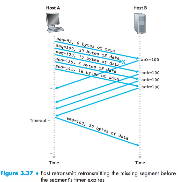
Fast Retransmit
A duplicate ACK is an ACK that reacknowledges a segment for which the sender has already received an earlier acknowledgment.
If the TCP sender receives three duplicate ACKs for the same data, it takes this as an indication that the segment following the segment has been lost.
In the case that three duplicate ACKs are received, the TCP sender performs a fast retransmit.
Go-Back-N or Selective Repeat?
Selective Acknowledgment: allows a TCP receiver to acknowledge out-of-order segments selectively rather than just cumulatively acknowledging the last correctly received, in order segment.
TCP’s error-recovery mechanism is probably best categorized as a hybrid of GBN and SR protocols.
Flow Control
Flow-Control Service:to eliminate the possibility of the sender overflowing the receiver’s buffer. Flow control is thus a speed-matching service, matching the rate at which the sender is sending against the rate at which the receiving application is reading.
LastByteRead: the number of the last byte in the data stream read from the buffer by the application process.
LastByteRcvd: the number of the last byte in the data stream that has arrived from the network and has been placed in the receive buffer.
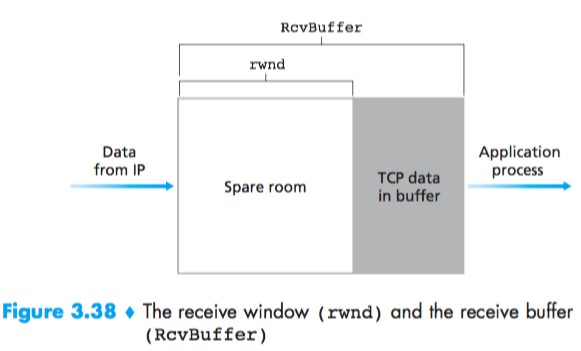
$$rwnd = RcvBuffer – [LastByteRcvd – LastByteRead]$$
Receiver tells Sender how much spare room it has in the connection buffer by placing its current value of rwnd in the receive window field of every segment it sends to Sender:
$$LastByteSent – LastByteAcked <= rwnd$$
But Sender is never informed that some space has opened up in Receiver receive buffer:The TCP specification requires Sender to continue to send segments with one data byte when Receiver’s rwnd is zero. These segments will be acknowledged by the receiver. Eventually the buffer will begin to empty and the acknowledgments will contain a nonzero rwnd value.
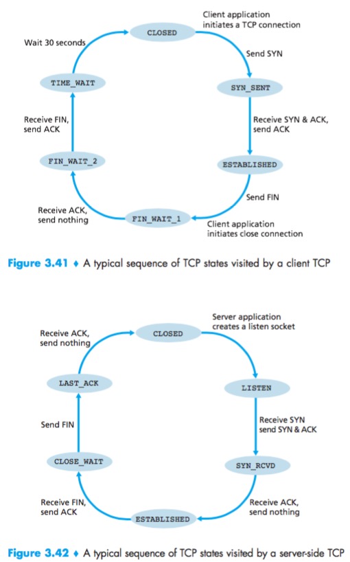
TCP Connection Management
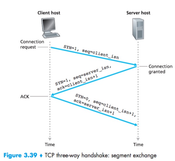
Three-way handshake
- The client first sends a special TCP segment to the server. This special segment contains no application-layer data. But one of the flag bits in the segment’s header, the SYN bit, is set to 1. For this reason, this special segment is referred to as a SYN segment(client_isn). In addition, the client randomly chooses an initial sequence number and puts this number in the sequence number field of the initial SYN segment in order to avoid certain security attacks.
- The server extracts the SYN segment from the datagram, allocates the TCP buffers and variables to the connection, and sends a connection-granted segment to the client TCP.This connection-granted segment also contains no application-layer data. However, it does contain three important pieces of information in the segment header. First, the SYN bit is set to 1. Second, the acknowledgment field is set to client_isn+1. Finally, the server chooses its own initial sequence number (server_isn) and puts this value in the sequence number field of the TCP segment header.
- Upon receiving the SYNACK segment, the client also allocates buffers and variables to the connection. The client host then sends the server yet another segment; this last segment acknowledges the server’s connection-granted segment (the client does so by putting the value server_isn+1 in the acknowledgment field of the TCP segment header). The SYN bit is set to zero, since the connection is established. This third stage of the three-way handshake may carry client-to-server data in the segment payload.
Four-way wave
- The client send a special TCP segment which has a flag bit in the segment’s header, the FIN bit set to 1.
- When the server receives this segment, it sends the client an ACK in return.
- The server then sends its own shutdown segment, which has the FIN bit set to 1.
- Finally, the client acknowledges the server’s shutdown segment. At this point, all the resources in the two hosts are now deallocated.
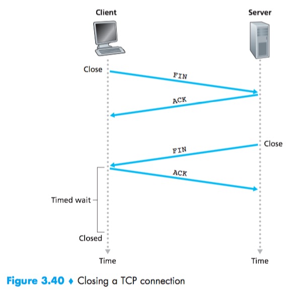
The time spent in the TIME_WAIT state is implementation-dependent, but typical values are 30 seconds, 1 minute, and 2 minutes.
THE SYN FLOOD ATTACK
Dos(Denial of Service) Attack:known as the SYN flood attack, the attacker(s) send a large number of TCP SYN segments, without completing the third handshake step. With this deluge of SYN segments, the server’s connection resources become exhausted as they are allocated for half-open connections; legitimate clients are then denied service.
An effective defense known as SYN cookies:
- The server creates an initial TCP sequence number that is a complicated function (hash function) of source and destination IP addresses and port numbers of the SYN segment, as well as a secret number only known to the server;
- For a legitimate ACK, the value in the acknowledgment field is equal to the initial sequence number in the SYNACK (the cookie value in this case) plus one. If it is matched, the server concludes that the ACK corresponds to an earlier SYN segment and is hence valid;
- If the client does not return an ACK segment, then the original SYN has done no harm at the server, since the server hasn’t yet allocated any resources in response to the original bogus SYN.
Principles of Congestion Control
Congestion control in the available bit-rate (ABR) service in asynchronous transfer mode (ATM) networks.
The Causes and the Costs of Congestion
Scenario 1: Two Senders, a Router with Infinite Buffers
Per-Connection Throughput:number of bytes per second at the receiver.
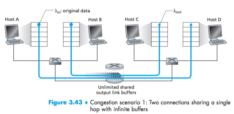
No matter how high Hosts A and B set their sending rates, they will each never see a throughput higher than R/2.
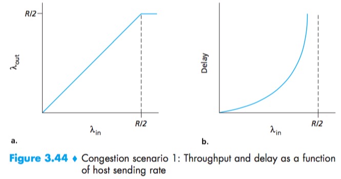
One cost of a congested network—large queuing delays are experienced as the packet-arrival rate nears the link capacity.
Scenario 2: Two Senders and a Router with Finite Buffers
$A_{in}^{‘}$ is sometimes referred to as the offered load to the network.
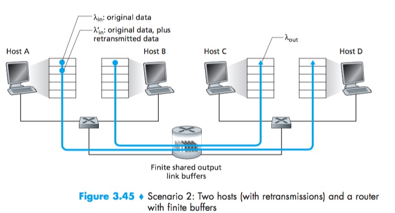
Another cost of a congested network—the sender must perform retransmissions in order to compensate for dropped (lost) packets due to buffer overflow.
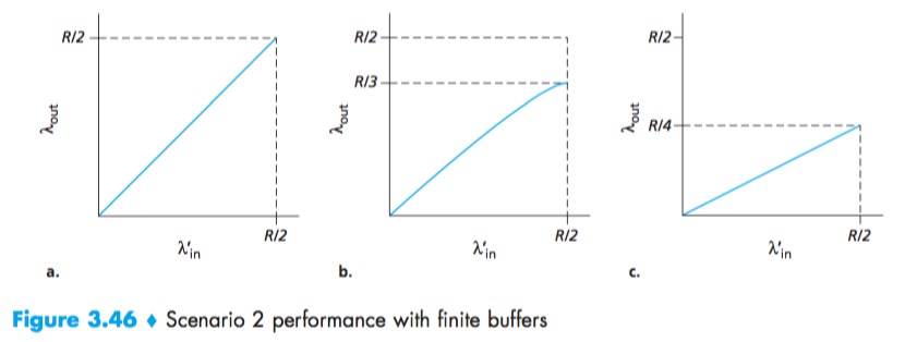
- a:Host A is able to somehow determine whether or not a buffer is free in the router and thus sends a packet only when a buffer is free;
- b:The sender retransmits only when a packet is known for certain to be lost(timeout large enough);
- c:The sender may time out prematurely and retransmit a packet that has been delayed in the queue but not yet lost.
Another cost of a congested network—unneeded retransmissions by the sender in the face of large delays may cause a router to use its link bandwidth to forward unneeded copies of a packet.
Scenario 3: Four Senders, Routers with Finite Buffers, and Multihop Paths
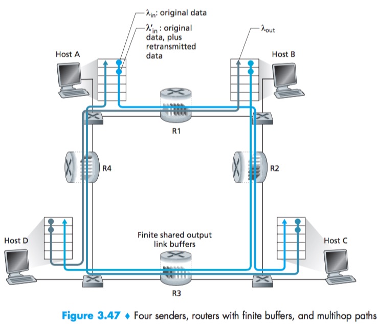
An empty buffer at R2 is immediately filled by a B–D packet, and the throughput of the A–C connection at R2 goes to zero.
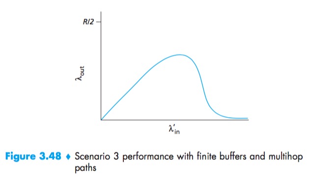
Another cost of dropping a packet due to congestion—when a packet is dropped along a path, the transmission capacity that was used at each of the upstream links to forward that packet to the point at which it is dropped ends up having been wasted.
Approaches to Congestion Control
Congestion-control approaches:
- End-to-end congestion control:the network layer provides no explicit support to the transport layer for congestion-control purposes(TCP).
- Network-assisted congestion control:network-layer components (that is, routers) provide explicit feedback to the sender regarding the congestion state in the network(XCP).
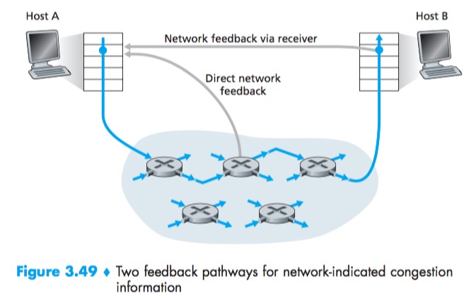
For network-assisted congestion control, congestion information is typically feed back from the network to the sender in one of two ways:
- Direct feedback may be sent from a network router to the sender. This form of notification typically takes the form of a choke packet.
- The second form of notification occurs when a router marks/updates a field in a packet flowing from sender to receiver to indicate congestion. Upon receipt of a marked packet, the receiver then notifies the sender of the congestion indication. Note that this latter form of notification takes at least a full round-trip time.
Network-Assisted Congestion-Control Example: ATM ABR Congestion Control
ATM ABR Congestion Control—a protocol that takes a network-assisted approach toward congestion control.
Fundamentally ATM takes a virtual-circuit(VC) oriented approach toward packet switching(this means that each switch on the source-to-destination path will maintain state about the source-to-destination VC). This per-VC state allows a switch to track the behavior of individual senders (e.g., tracking their average transmission rate) and to take source-specific congestion-control actions (such as explicitly signaling to the sender to reduce its rate when the switch becomes congested). This per-VC state at network switches makes ATM ideally suited to perform network-assisted congestion control.
ABR has been designed as an elastic data transfer service in a manner reminiscent of TCP. When the network is underloaded, ABR service should be able to take advantage of the spare available bandwidth; when the network is congested, ABR service should throttle its transmission rate to some predetermined minimum transmission rate.
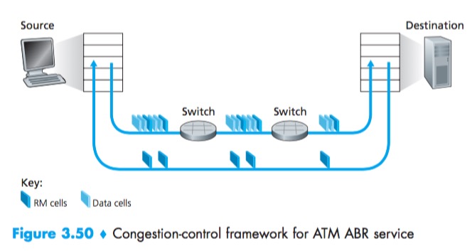
With ATM ABR service, data cells are transmitted from a source to a destination through a series of intermediate switches. Interspersed with the data cells are resource-management cells(RM cells); these RM cells can be used to convey congestion-related information among the hosts and switches. When an RM cell arrives at a destination, it will be turned around and sent back to the sender (possibly after the destination has modified the contents of the RM cell). It is also possible for a switch to generate an RM cell itself and send this RM cell directly to a source. RM cells can thus be used to provide both direct network feedback and network feedback via the receiver.
ABR provides three mechanisms for signaling congestion-related information from the switches to the receiver:
- EFCI bit. Each data cell contains an explicit forward congestion indication (EFCI) bit. A congested network switch can set the EFCI bit in a data cell to 1 to signal congestion to the destination host. The destination must check the EFCI bit in all received data cells. When an RM cell arrives at the destination, if the most recently received data cell had the EFCI bit set to 1, then the destination sets the congestion indication bit (the CI bit) of the RM cell to 1 and sends the RM cell back to the sender. Using the EFCI in data cells and the CI bit in RM cells, a sender can thus be notified about congestion at a network switch.
- CI and NI bits.The sender-to-receiver RM cells have a congestion indication (CI) bit and a no increase (NI) bit that can be set by a congested network switch. Specifically, a switch can set the NI bit in a passing RM cell to 1 under mild congestion and can set the CI bit to 1 under severe congestion conditions. When a destination host receives an RM cell, it will send the RM cell back to the sender with its CI and NI bits intact.
- ER setting. Each RM cell also contains a 2-byte explicit rate (ER) field. A congested switch may lower the value contained in the ER field in a passing RM cell. In this manner, the ER field will be set to the minimum supportable rate of all switches on the source-to-destination path.
An ATM ABR source adjusts the rate at which it can send cells as a function of the CI, NI, and ER values in a returned RM cell.
TCP Congestion Control
TCP must use end-to-end congestion control rather than net- work-assisted congestion control, since the IP layer provides no explicit feedback to the end systems regarding network congestion.
The congestion window, denoted cwnd, imposes a constraint on the rate at which a TCP sender can send traffic into the network.
$$LastByteSent – LastByteAcked <= min{cwnd, rwnd}$$
The sender’s send rate is roughly cwnd/RTT bytes/sec. By adjusting the value of cwnd, the sender can therefore adjust the rate at which it sends data into its connection.
If ACK arrive at a high rate, then the congestion window will be increased more quickly. Because TCP uses acknowledgments to trigger (or clock) its increase in congestion window size, TCP is said to be self-clocking.
TCP uses the following guiding principles:
- A lost segment implies congestion, and hence, the TCP sender’s rate should be decreased when a segment is lost.
- An acknowledged segment indicates that the network is delivering the sender’s segments to the receiver, and hence, the sender’s rate can be increased when an ACK arrives for a previously unacknowledged segment.
- Bandwidth probing.The TCP sender thus increases its transmission rate to probe for the rate that at which congestion onset begins, backs off from that rate, and then to begins probing again to see if the congestion onset rate has changed.
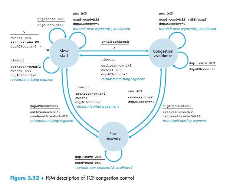
TCP congestion-control algorithm:(1) slow start, (2) congestion avoidance, and (3) fast recovery.
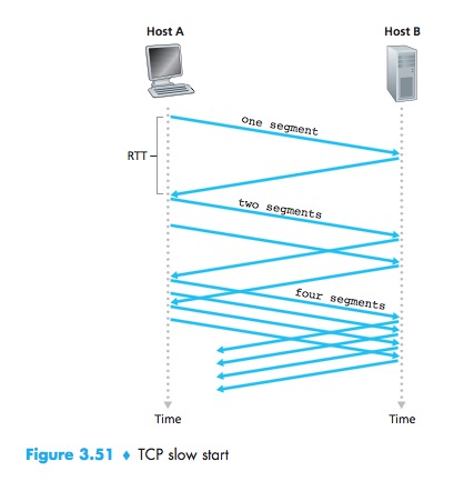
Slow Start
In the slow-start state, the value of cwnd begins at 1 MSS and increases by 1 MSS every time a transmitted segment is first acknowledged.The TCP send rate starts slow but grows exponentially during the slow start phase.
First, if there is a loss event indicated by a timeout, the TCP sender sets the value of cwnd to 1 and begins the slow start process anew. It also sets the value of a second state variable, ssthresh (shorthand for “slow start threshold”) to cwnd/2—half of the value of the congestion window value when congestion was detected. The second way in which slow start may end is directly tied to the value of ssthresh. When the value of cwnd equals ssthresh, slow start ends and TCP transitions into congestion avoidance mode. The final way in which slow start can end is if three duplicate ACKs are detected, in which case TCP enters the fast recovery state.
TCP Splitting:breaking the TCP connection at the front-end server to optimize the performance of cloud service. The client establishes a TCP connection to the nearby front-end, and the front-end maintains a persistent TCP connection to the data center with a very large TCP congestion window.
Congestion Avoidance
On entry to the congestion-avoidance state, the value of cwnd is approximately half its value when congestion was last encountered and increases the value of cwnd by just a single MSS every RTT(whenever a new acknowledgment arrives).
TCP’s congestion-avoidance algorithm behaves the same when a timeout occurs. As in the case of slow start: The value of cwnd is set to 1 MSS, and the value of ssthresh is updated to half the value of cwnd when the loss event occurred.
If a triple duplicate ACK event occurs, TCP halves the value of cwnd (adding in 3 MSS for good measure to account for the triple duplicate ACKs received) and records the value of ssthresh to be half the value of cwnd. The fast-recovery state is then entered.
Fast Recovery
In fast recovery, the value of cwnd is increased by 1 MSS for every duplicate ACK received for the missing segment that caused TCP to enter the fast-recovery state. Eventually, when an ACK arrives for the missing segment, TCP enters the congestion-avoidance state after deflating cwnd. If a timeout event occurs, fast recovery transitions to the slow-start state after performing the same actions as in slow start and congestion avoidance: The value of cwnd is set to 1 MSS, and the value of ssthresh is set to half the value of cwnd when the loss event occurred.
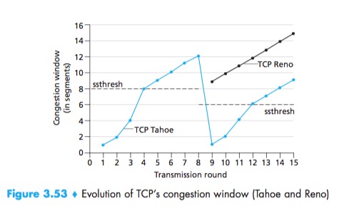
TCP Tahoe:an early version of TCP, unconditionally cut its congestion window to 1 MSS and entered the slow-start phase after either a timeout-indicated or triple-duplicate-ACK-indicated loss event. The newer version of TCP, TCP Reno, incorporated fast recovery.
FSM
TCP Congestion Control: Retrospective
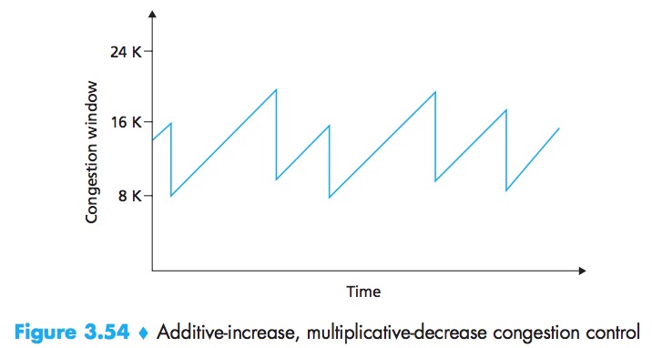
Ignoring the initial slow-start period when a connection begins and assuming that losses are indicated by triple duplicate ACKs rather than timeouts,TCP congestion control is often referred to as an additive-increase, multiplicative-decrease (AIMD) form of congestion control.
Macroscopic Description of TCP Throughput
$$average\ throughput\ of\ a\ connection = \frac{0.75 * W}{RTT}$$
TCP Over High-Bandwidth Paths
The throughput of a TCP connection as a function of the loss rate (L), the round-trip time (RTT), and the maximum segment size (MSS):
$$average\ throughput\ of\ a\ connection = \frac{1.22 * MSS}{RTT\sqrt(L)}$$
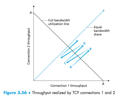
Fairness
A congestion-control mechanism is said to be fair if the average transmission rate of each connection is approximately R/K; that is, each connection gets an equal share of the link bandwidth.
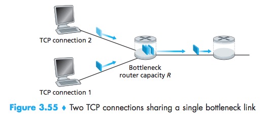
In particular, it has been shown that when multiple connections share a common bottleneck, those sessions with a smaller RTT are able to grab the available bandwidth at that link more quickly as it becomes free (that is, open their congestion windows faster) and thus will enjoy higher throughput than those connections with larger RTTs.
Fairness and UDP
From the perspective of TCP, the multimedia applications running over UDP are not being fair—they do not cooperate with the other connections nor adjust their transmission rates appropriately. Because TCP congestion control will decrease its transmission rate in the face of increasing congestion (loss), while UDP sources need not, it is possible for UDP sources to crowd out TCP traffic.
Fairness and Parallel TCP Connections
But even if we could force UDP traffic to behave fairly, the fairness problem would still not be completely solved. This is because there is nothing to stop a TCP-based application from using multiple parallel connections.
Because Web traffic is so pervasive in the Internet, multiple parallel connections are not uncommon.